
The Future of Fuel Cells
|
CONTENTS 11pg 57K 11fig 1. Abstract 2. Introduction 3. Background 4. How does a fuel cell work? 5. Types of fuel cells 6. Fuel cells for electric power production 7. Fuel cells for transportation 8. Solid oxide fuel cell (SOFC) 9. Direct alcohol fuel cell (DAFC) 10. Polymer electrolyte fuel cell (PEFC) 11. Phosphoric acid fuel cell (PAFC) 12. Molten carbonate fuel cell (MCFC) 13. Alkaline fuel cell (AFC) 14. Fuels 15. Forms of energy 16. Thermal temperature vs chemical temperature 17. Fuel cells vs heat engines 18. Second law analysis of fuel cells 19. Conclusions 20. Notes 21. References 22. Symbols 23. Revision History >>>Copyright 2023Mar05 by Ben Wiens...energy scientist
1. ABSTRACT
2. INTRODUCTION
3. BACKGROUND
4. HOW A FUEL CELL WORKS
Fig 1 Alkaline fuel cell often uses hydrogen and oxygen as fuel The alkaline fuel cell as shown in Fig 1 is one of the oldest and most simple type of fuel cell. This is the type of fuel cell that has been used in space missions for some time. Hydrogen and oxygen are commonly used as the fuel and oxidant. The electrodes are made of porous carbon plates which are laced with a catalyst...which is a substance that accelerates chemical reactions. The electrolyte is potassium hydroxide. At the anode, the hydrogen gas combines with hydroxide ions to produce water vapor. This reaction results in electrons that are left over. These electrons are forced out of the anode and produce the electric current. At the cathode, oxygen and water plus returning electrons from the circuit form hydroxide ions which are again recycled back to the anode. The basic core of the fuel cell consisting of the manifolds, anode, cathode and electrolyte is generally called the stack.
5. TYPES OF FUEL CELLS |

| Type | Abbreviation | Operating temp | Uses |
| Solid Oxide | SOFC | 500-1000°C | All sizes of CHP |
| Direct Alcohol | DAFC | 50-100°C | Buses, cars, appliances, small CHP |
| Polymer Electrolyte | PEFC | 50-100°C | Buses, cars |
| Phosphoric Acid | PAFC | 200°C | Medium CHP |
| Molten Carbonate | MCFC | 600°C | Large CHP |
| Alkaline | AFC | 50-250°C | Used in space vehicles |
|
Fig 2 Different types of fuel cells
Scientists keep changing their minds every few years about which of the above fuel cells will be the most popular in the future. As of 2008 there are three types of fuel cells that appear to be the most promising. The Solid Oxide Fuel Cell or SOFC is the most likely contender for both large and small electric powerplants in the 1 kw and above size. The Direct Alcohol Fuel Cell or DAFC appears to be the most promising as a battery replacement for portable applications such as cellular phones and laptop computers. It is difficult to tell at this moment which fuel cell will be most practical for transportation applications such as automobiles and buses. The Polymer Electrolyte Fuel Cell PEFC is the most practical if we have a developed hydrogen economy. Many automobile manufacturers however believe that the DAFC will be much simpler than the PEFC so it will be the winner for vehicular applications. Others say that the much higher efficiency of the SOFC and its ability to use most any fuel will make it a logical choice for vehicular applications as well. Proponents claim the startup time problem of the SOFC can be overcome by using supercapacitor batteries for the first few minutes of operation.
6. FUEL CELLS FOR ELECTRIC POWER PRODUCTION
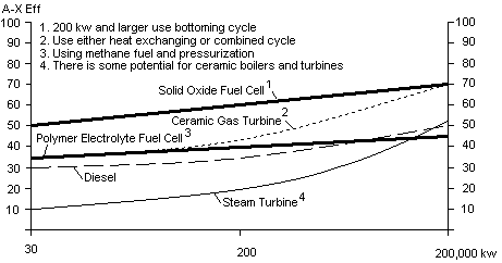
Fig 3 Chart showing projected efficiencies of different future electricity generating powerplants
There is a rapid trend in North America to deregulate the production of electric power. One of the benefits of deregulation is that it could promote CHP...combined heat and power, also known as cogeneration. North America will likely generate much of its electricity by burning fossil fuel for the next 10-40 years. CHP could conserve fuel by utilizing the thermal energy that is produced as a result of generating electricity. Unfortunately, in their quest to go totally green, many governments are outlawing many forms of cogeneration. This is a mistake in my opinion, because it will take many years to develop totally renewal forms of electric power.
7. FUEL CELLS FOR TRANSPORTATION
Fig 4 Estimated efficiencies [1] of different automobiles using liquid hydrocarbon fuel
Fuel cells are being proposed to replace Otto or Diesel engines because they could be reliable, simple, quieter, less polluting, and have even greater economy.
8. SOLID OXIDE FUEL CELL (SOFC)
Fig 5 Simple type [2] SOFC suitable for 1-30 kw powerplants
The Solid Oxide Fuel Cell is considered to be the most desirable fuel cell for generating electricity from hydrocarbon fuels. This is because it is simple, highly efficient, tolerant to impurities, and can at least partially internally reform hydrocarbon fuels.
9. DIRECT ALCOHOL FUEL CELL (DAFC)
Fig 6 A small simple 30 kw Direct Methanol Fuel Cell
Figure 6 illustrates a type of DMFC that could be used in a 30 kw system. Even smaller ones for use as battery replacements do away with the air blower and the separate methanol water tank and pump. Such fuel cells are not much different than batteries in construction. |


|
10. POLYMER ELECTROLYTE FUEL CELL (PEFC) The PEFC is considered the darling fuel cell by proponents of the hydrogen economy. Automobiles emitting pure water from their tailpipes are envisioned. It is not likely that there will be hydrogen pipelines supplying homes, businesses and service stations in the near future however. Many companies are proposing that PEFC systems would extract hydrogen from hydrocarbon fuels such as methanol or natural gas. While the efficiency of the PEFC when running on hydrogen and no air pressurization is high, practical systems that use fuel reforming and air compression suffer in efficiency. Small 30 kW AC powerplants will likely be 35% fuel to electricity efficient, 200 kW units 40% and large units 45%. Figure 4 shows that an automobile powerplant including an electric motor would have an efficiency of about 35%. There has been some progress made in storing hydrogen in different materials such as hydrides or carbon. If such materials can be perfected this would dramatically increase the chances for the PEFC success for automotive applications. The complex reformer would not be necessary, however unless hydrogen is universally available through pipelines across the country, the hydrogen would have to be manufactured locally by service stations. This is possible for larger city service stations but not really practical for small out of the way ones. The PEFC generally operates at 80°C which makes it ideal for small applications and allows reasonably inexpensive materials to be used. Unfortunately, this low a temperature is quite near the ambient temperature which hampers disposing of excess heat--present automobile engines dispose of heat at up to 100°C. A catalyst is also required to promote the chemical reaction at the low temperatures involved. Previously the platinum catalysts used in the stack made this type of fuel cell expensive. New techniques for coating very thin layers of catalyst on the polymer electrolyte have reduced the cost of the catalyst to around $150 per automobile. The PEFC is particular in that only hydrogen fuel can be used in the cell. Hydrocarbon fuels must be reformed carefully. Even small amounts of carbon monoxide in the cell can poison the catalyst--often permanently. If a reformer is used, this also requires a few minutes warm up time. Stored hydrogen must be used in the startup phase. Such problems make the PEFC running on stored hydrogen sound more appealing. A larger manufacturing plant running continuously has a much better chance of supplying very pure hydrogen. A liquid cooling system is required. This means that there is pure water inside the cells. Ballard has tested the fuel cell at below freezing temperatures and there was no damage to the stack. It appears that the stack coolant must be drained after shutdown. I do not know what repeated freeze-thaw cycling would do to the hydrated stack even if drained. Larger than 1 kw PEFC are generally pressurized to increase the chemical reaction at the low temperatures involved. Air compression to about 3 atmospheres or higher must be used for the fuel cell to have a reasonable power density. On small systems this results in a substantial loss of efficiency. The air compressors also add considerable complexity to the fuel cell. On automobiles and buses two air compressors are often used. One is a turbocharger and the second is a supercharger. Many experts feel that the DAFC will replace the PEFC once problems are solved. There is however a chance that a gasoline reformer will be perfected. If such a fuel cell system can be made to be reliable and inexpensive, then the PEFC will have a much better chance of being successful. Many experts however are not sure this is possible.
11. PHOSPHORIC ACID FUEL CELL (PAFC)
12. MOLTEN CARBONATE FUEL CELL (MCFC)
13. ALKALINE FUEL CELL (AFC)
14. FUELS
Fig 7 Different forms of energy shown in a chart
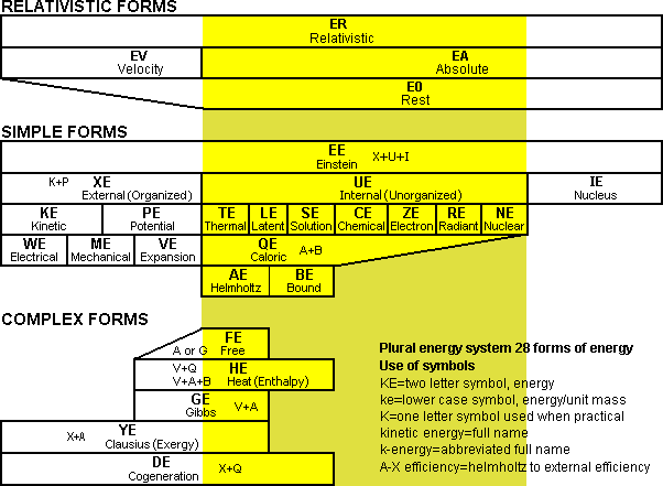
To properly evaluate different types of fuel cells it is desirable to understand basic theoretical energy concepts. To understand energy concepts, it is beneficial to have a proper naming system that covers all the basic types of different energy in the universe. This is because it is often difficult or impossible to convert certain types of energy into different forms. The system of energy used in this booklet is based on a plural energy system where all the different types of energy are two word forms such as chemical energy. The basis of this two word naming system is borrowed from chemistry, however typically it is not labeled as the plural energy system. Engineers do not like to use this chemistry naming system, however it is the simplest and easiest to understand. The plural energy system is shown as a bar chart in Fig 7. At the head of the chart of "simple forms" is einstein energy which is...a term for the concept of the total energy in the universe or a particular system. When referring to the fact that energy is conserved in the universe it should be mentioned that it is einstein energy that is conserved, because other forms may not be. All einstein energy can be logically divided into either external energy, internal energy, or nucleus energy. 16. THERMAL TEMPERATURE AND CHEMICAL TEMPERATURE
Fig 8 Virtual photons are closely coupled and real photons travel alone through space
A fuel cell creates electricity, which is a form of external energy, directly from the energy in chemical fuels without an intermediate conversion into thermal energy. When a hydrogen atom bonds to an oxygen molecule, not as much total energy is required in the newly formed water molecule as in the separate hydrogen and oxygen molecules. In this exothermic chemical reaction, the excess energy produced is not initially dribbled out in randomly sized quantities of energy. Rather one virtual photon is produced for each new molecule produced. This virtual photon preserves the helmholtz energy produced in the reaction by storing the largest amount of energy possible in each virtual photon. This is illustrated in Fig 8.
17. FUEL CELLS vs HEAT ENGINES
Fig 9 Heat engines are theoretically at a disadvantage compared to fuel cells
The virtual photons that are transferred during the chemical reactions in a fuel cell have a very high chemical temperature somewhere between 3,500° and 20,000° Kelvin. It is this extremely high chemical temperature that allows the fuel cell to be theoretically so efficient. Generally textbooks relate Carnot's Law only to the amount of external energy that can be extracted from thermal energy systems. The same law however does apply to all internal energy systems whether nuclear, chemical, or thermal etc. The amount of external energy that can be extracted from all types of internal energy is called the carnot ratio. The carnot ratio for virtual photons of 3,500°K is however about 92% under normal conditions. This is much higher than for real photons in a gas turbine with a mean temperature of 1000°K and a carnot ratio of 72%. The carnot ratio is based on a particular ambient temperature of the surroundings. The carnot ratio only relates to the absolute temperature scale where 0°C=273.15°K degrees.
18. SECOND LAW ANALYSIS OF FUEL CELLS
Fig 10 Clausius energy loss diagram for proposed 30 kw AC powerplants operating on hydrocarbon fuel
In Fig 10 the clausius energy efficiency of three proposed fuel cells are compared when operating on hydrocarbon fuel. The fuel cell process is divided into six subsystems. In each subsystem there are inefficiencies involved that reduce the clausius energy that is left in the system. In all cases, the electricity that is extracted is still considered to be part of the clausius energy of the system. It appears that the SOFC 30 kw system will have an efficiency of 1.4 times that of the PEFC and 1.3 times that of the DMFC. |


| SOFC | PEFC | DMFC | |||||||||||||||||||||||||||||||||||||||||||||||||||||||||||||||||||||||||||||
|---|---|---|---|---|---|---|---|---|---|---|---|---|---|---|---|---|---|---|---|---|---|---|---|---|---|---|---|---|---|---|---|---|---|---|---|---|---|---|---|---|---|---|---|---|---|---|---|---|---|---|---|---|---|---|---|---|---|---|---|---|---|---|---|---|---|---|---|---|---|---|---|---|---|---|---|---|---|---|---|
Subsystem| Y-eff | BE | YE | Y-eff | BE | YE | Y-eff | BE | YE
| 0. Hydrocarbon fuel | - | - | 100.0 | - | - | 100.0 | - | - | 100.0
| 1. Reformer/Burner | 95% | 5.0 | 95.0 | 80% | 20.0 | 80.0 | 100% | 0 | 100.0
| 2. Stack electrical | 86% | 14.0 | 82.0 | 64% | 28.5 | 51.5 | 47% | 53.2 | 46.8
| 3. Stack thermal | 0% | 27.0 | 55.0 | 0% | 1.5 | 50.0 | 0% | 1.4 | 45.4
| 4. Pressurization | 98% | 1.0 | 54 | 78% | 10.8 | 39.2 | 90% | 4.6 | 40.8
| 5. System | 98% | 1.0 | 53.0 | 95% | 2.0 | 37.2 | 98% | 0.8 | 40.0
| 6. Inverter | 94% | 3.0 | 50.0 | 94% | 2.2 | 35.0 | 94% | 2.5 | 37.5
|
|
|
Fig 11 Clausius energy efficiency of subsystems in 30 kw AC powerplants operating on hydrocarbon fuel
19. CONCLUSIONS
20. NOTES
21. REFERENCES
22. SYMBOLS
23. REVISION HISTORY
COPYRIGHT © 1999-2023 All rights reserved |